Each part below is contained within a collapsable/expandable bar.
PART I. Intro: 360 HDR Panoramas
Overview
Our objective is to shoot an HDR 360 panorama which can be used for image-based lighting (IBL). That means we need to shoot several exposures of each view which will then be combined into a HDRI (high dynamic range image), and also that we need to shoot several views so that each HDRI can be stitched together into a seamless 360 panorama.
To capture our 360 degree panorama, we will shoot with a 8mm fisheye lens, giving us a 180 degree view, taking 4 images at 90 degree rotations (giving us plenty of overlap), and 2 additional images shot straight up and down. To avoid parallax we will take these pictures on a tripod with a Nodal Ninja. Each of these steps is explained in more detail below.
To get a full dynamic range we will shoot 10 exposures for each view. With 10 exposures for 6 views that adds up to 60 images for each HDR panorama, which is why we need a good amount of space on our memory card, especially if we want to shoot in raw.
Looking into the future, Google has developed a special camera which is designed to take 360 HDR panoramas, called the Iris360. It is not available yet, but is scheduled to be available for purchase Nov 2015. It is unclear whether the Iris360 can output multiple exposures.
Equipment
For a HDR 360 panorama shoot we use the following equipment (all available for checkout from the Video Lab)
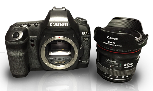
DSLR camera: Canon 5D Mark II
Fisheye lens: Canon 8-15mm f/4L
Panoramic head: Nodal Ninja 4
Tripod with ball head: Manfrotto 190XB tripod with Oben BE-117 Ball Head Mount
SD or CF cards: 16GB Memory Card with Magic Lantern Firmware
The Nodal Ninja is a brand of panoramic head. A pano head allows us to rotate the camera on a tripod without creating parallax by shifting the center of rotation. This is important because otherwise the different angles of our panorama will not stitch together properly because of parallax.
The basic idea is that if we rotate the camera on the tripod normally, this is like turning your head, which results in parallax. You can try this by holding your finger in front of your face, lining it up with an object in the distance. Close one eye and turn your head. Notice how the objects behind your finger do not stay lined up when you turn your head. That's parallax. So we instead need to rotate the camera around the "entrance pupil" of our camera, similar to how when your eye rotates there is no parallax. Try the same experiment with your finger, this time just rotating your one open eye to the left and right. The object behind stays lined up. No parallax!
Nodal Ninja Assembly
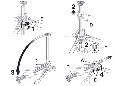
NN4 comes preassembled in two parts - upper and lower assembly. Place the vertical arm assembly on the lower rail, and secure with the vertical rail knob.
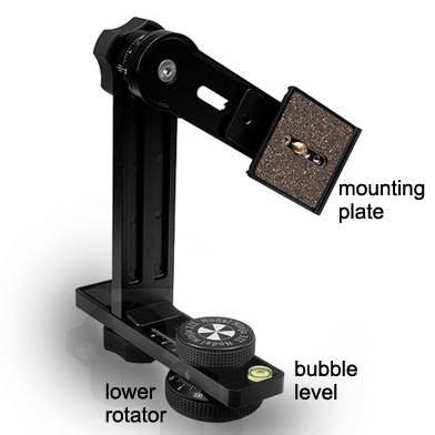
Fig 1: The Nodal Ninja 4
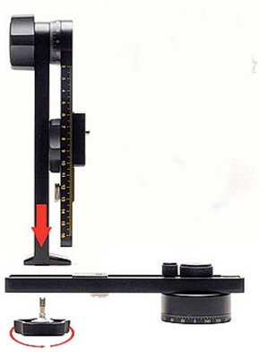
Fig 2: Basic Assembly
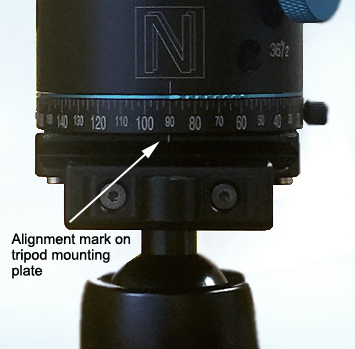
Once the arms are assembled, attach the tripod mounting plate to the lower rotator of the Nodal Ninja (see fig 1 above), aligning the center markings on both so they line up (fig 2). Mount the Nodal Ninja to the tripod and adjust the tripod ball-head so that the bubble level (fig 1) on the Nodal Ninja is centered.
Fig 2: Aligning the tripod mount with the Nodal Ninja base
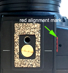
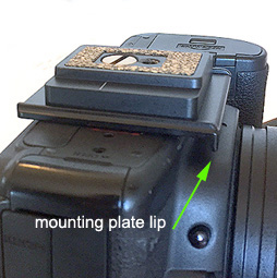
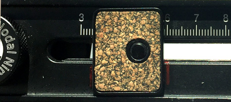
Next, unscrew the Nodal Ninja mounting plate (fig 1) and attach it to the camera's tripod socket, using the penny to screw it in. Note that the camera has a red line indicating the proper alignment of the mounting plate (fig 4 below). Note also that the direction of the mounting plate is important. In the image below (fig 5) you can see the lip of the mounting plate, indicating the correct direction. Once the mounting plate is attached to the camera, it can then be attached to the Nodal Ninja's vertical arm.
Fig 4: Aligning the mounting plate
Fig 5: The lip of the mounting plate
Alignment
Aligning the Nodal Ninja involves two steps. The first is the vertical alignment, and the second is lateral alignment to find the no-parallax point of the lens. Both are detailed below, and involve a lot of complex calibration. The good news is that once these points have been identified for your lens you don't need to do it again, and further since these points have been marked on the Nodal Ninja you can simply jump to the rail stops section where this is described, and skip the alignment steps below.
Vertical Alignment
With the camera/lens mounted, rotate the upper rail so it is perpendicular to the ground. Point the camera directly down, making sure the barrel of the lens is in line with the upper rail.
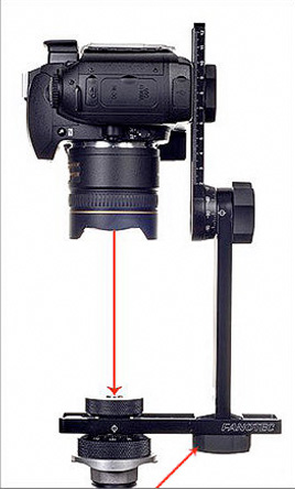
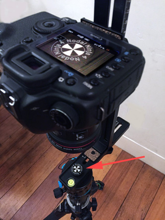
Loosen the lower vertical rail knob (indicated in the image below with the diagonal arrow), slide the vertical and upper assembly back and forth on the lower rail unit until the camera/lens is positioned directly over the lower rotator knob (marked with the Nodal Ninja bulls-eye shown below).
A good way to do this is to zoom the camera in so you can get it perfectly aligned. Begin by zooming the camera to 15mm (by turning the lens). Next click the live mode button (see the Camera Diagram below), and press the zoom button twice (Camera Diagram). This will give you a 10x zoom, allowing you to see that the lens is lined up with the bullseye.
Fig 6: Vertical Alignment
Fig 7: Live view of "bulls-eye" with 10x zoom
Finding the No Parallax Point (NPP)
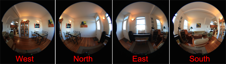
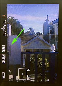
Make sure the camera lens is set to 8mm (full 180 fisheye), and rotate the upper arm to the 90 degree mark (horizontal). Position the camera so it is viewing two objects - one nearer than the other. For example, in the images below we are looking through a window directly in front of the camera with a piece of tape that is lined up vertically with the house in the distance. To see this properly you'll want to zoom the live mode view in 10x as described above.
To find the no parallax point, rotate the Nodal Ninja to the left (counter-clockwise) and right (clockwise), noting if the near object (the tape) goes out of alignment with the far object (the house). If you turn to the left (CCW) and the alignment shifts to the right (i.e. in the opposite direction) this means you need to move the camera back on the rail (towards you). Conversely, if you turn to the right (CW) and the alignment shifts to the left (i.e. in the same direction) this means you need to move the camera forward on the rail (away from you).
So the rule is:
Opposite shift = Move back
Same direction = Move forward.
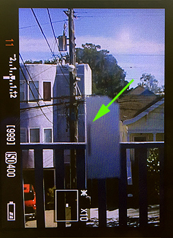
Our goal is the find the position where there is no shift in alignment. This is the no parallax point, pictured below.
Fig 8: Rotating to the left (CCW)
Fig 9: Strait-on view of near/far objects
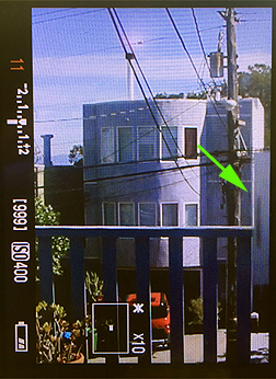
Fig 10: Rotating to the right (CW)
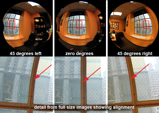
Because we are zoomed in, we can only rotate the camera so far before our near-object goes out of frame. So to fully test the parallax we will need to do a further test. Take three photos, the first facing forward, the second and third rotating the camera left and right 45 degrees (you can set the Nodal Ninja to lock at 45 degree angles for this purpose). Next view your three photos zooming in to see the alignment.
Fig 11: Comparing photos of fisheye images at 45 degree angles.
In the above example (fig 11) we are aligning the bar on the window with the building behind it. Notice that there is no parallax shift. Note too that as we move away from the image center the image bends with the circular lens. Technically on a fisheye lens there is no single entrance pupil point, as the location of the entrance pupil shifts as the viewing angle moves away from the center (that means rather than a point, it is more like the shape of a trumpet). Because of this, some people prefer to speak of a "least parallax point" rather than a "no parallax point".
For our purposes what matters most is that we get the parallax just right on the spot where our images will be stitched together. Since we will be taking our lateral images at 90 degree rotations, we test our no-parallax point at 45 degree angles, which is the seam where the 90 degree shots will overlap.
Rail Stops
Once the vertical alignment and no parallax point (NPP) have been found, we can mark their positions with the rail-stops so that in the future we can simply use these. That means we only need to calculate this once, and can then use the railstop settings in the future which will always be correct for this camera lens. Note that the proper position of the rail-stops has been marked with red lines to the left and right for both the vertical and horizontal arms of the Nodal Ninja.
Fig 12: Railstop position marked with red lines
PART III. Camera Setup
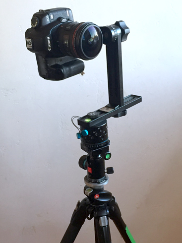
Fig 13: Canon 5D Mark II with Canon 8-15mm f/4L Fisheye lens.
Let's begin with some camera settings. With the exception of the focal length zoom, which is set on the lens itself, you can access these settings on the 5D from the main display screen using the "multi-controller" joystick (see the Camera Diagram). Press it once to display the menu, and then use it to navigate to the various settings described below. Consult the manual for more details.
Zoom Focal Distance: 8mm
Aperture (F-Stop): f8 or f11
ISO: 400
Metering: Evaluative
Continuous shooting: Single or Continuous
White Balance: Set manually according to scene
Image Format: Large (high quality ) JPG
Color Space: sRGB
Fig 14: Camera buttons (white) and Display settings (red).
AEB & Magic Lantern
To shoot HDR images we will need to take multiple exposures of each view. When manually changing the exposure settings, it is very easy to bump the camera, misaligning the images. To solve this we use AEB (automatic exposure bracketing). AEB shoots multiple exposures, bracketing them above and below the main exposure.
Most cameras allow you to shoot 3 exposures (one above and one below the exposure setting), this is the case with the Canon 5D Mark II DSLR which we use. For HDR, however, we want more exposures. For this reason we use Magic Lantern firmware. Magic Lantern allows us to expand the ability of the Mark II to shoot automatic exposure bracketing (AEB) up to 12 exposures.
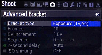
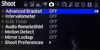
To access the Magic Lantern menu, click the "trash" button on the camera (see Camera Diagram above). You can then navigate through the menu using the two dials on the top and back of the camera. Navigate to the "shoot" menu page, and select Advanced Bracketing at the top.
Fig 15: Magic Lantern's "shoot" menu page.
To enter its settings press the "picture style select" button on the camera (see the Camera Diagram above). In the settings dialog enter the following:
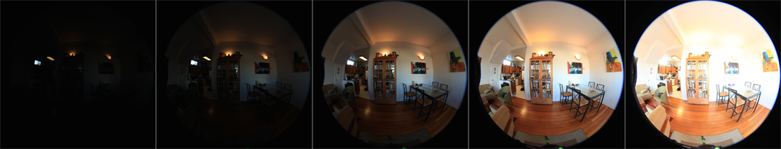
This will give us 10 pictures, incrementing each image by 1 exposure step (EV stands for exposure value). The sequence 0 - + -- ++ means the camera exposure value we choose will be in the middle, bracketing the other exposures above and below it. Because there is an automatic 2-second delay, we don't need to worry about shaking the camera when we press the shutter.
The exposure setting "Exposure (Tv, Ae)" means that it will keep the aperture constant (the F-number), and bracket the exposure by varying the shutter speed (Tv stands for "time value" referring to the shutter speed. Ae stands for "automatic exposure"). We want to keep the aperture constant because this affects the depth of field (DOF), and if the DOF changed with each exposure the images would not line up together into a HDRI (high dynamic range image) since some would be defocused. So we instead modify the exposure by changing the shutter speed. Shutter speed affects motion blur, but ideally nothing is moving in our panorama (moving leaves and clouds can present a problem).
PART IV. The Shoot
Scene-Dependent Camera Settings
For our shoot we need to set the white balance, shutter speed, and focus according to our scene conditions. All of these should be set manually so they remain consistent across all of our photos.
We can use a little trick to get the camera to auto-focus and also automatically determine the proper shutter speed needed for our chosen aperture to get a properly exposed image:
Shutter Speed
Set the camera mode dial to Av (aperture priority)
Press the shutter button halfway down. This will automatically set the shutter speed, which can be viewed in the LCD display on top of the camera.
Make a mental note of the shutter value, switch the mode to manual, and set the shutter speed to that value (if the LCD says 8 for example, that means the shutter needs to be set to 1/8 sec).
Focus
With the camera in AF mode, hit the Auto Focus button (AF-ON)
Switch the camera to manual focus. Now we have correct focus locked down.
Note that with a fisheye lens, when shooting objects that are 1.5 meters or nearer, the photo will be in focus at the center, and fuzzy at the edges. Conversely, when shooting subjects at 1.5 meters and beyond, the lens is essentially at the infinity focus position, i.e. at hyperfocal distance, so that everything is in focus. This is commonly the case with HDR panoramas, including indoor shots.
The Shoot
Now that everything is set up, we are ready to shoot our images. We will take 4 shots, rotating the camera at 90 degree stops. Because we have set the AEB, each shot will take 10 exposures, for a total of 40 images. Next we will rotate the Nodal Ninja to shoot straight up (this is referred to as the zenith), and strait down (the nadir).
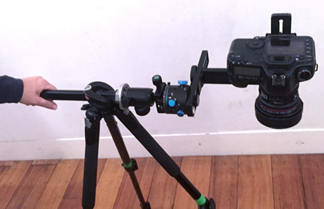
Further, when we shoot the nadir, the tripod will be in view, which will present a problem when stitching our 360 panorama. For this reason we will take an additional shot of the area under our tripod. To do this, we will take advantage of a feature of the Manfrotto tripod, turning it sideways by sliding the center column horizontally as shown below (fig 17). Note that you need to press the bottom of the center column to unlock it, as shown in step 2 of the diagram below.
Important: Because the tripod can become imbalanced when in this position, make sure to hold the end of the center column, as shown below, so it doesn't accidentally fall over (fig 18).
Fig 17: Sliding the center column horizontally
Fig 18: Make sure to hold on so it does not fall over!
PART V. Stitching
Stitching with PTgui
The video below take you through the steps for stitching your HDR pano. Before you do this however you will need to enable the advanced settings in PTgui.
Simply click the "advanced" button on top right corner of "project assistant" tab. This will enable all of the tabs you see in the video.
The steps in the above video are described below with links to the timecode for each part.
Lateral exposures
Fig 19: Lateral fisheye images (cropped).
Load the images PTgui can use the exif data in the images to determine how to group the images and order the
exposures automatically (Fig. 20).
So you just select all the lateral exposures (excluding the nadir and zenith) and drag and drop them in. This is shown in
3 min 3 sec of the above video.
Fig 20: A simplified exposure set showing 2 EV stops (Full set is 10 exposures using 1 EV stop).
Align the images Click the "allign images" button, and check "enable HDR and link bracketed images" and "true HDR"
in its options window.
The images will be automatically aligned. You can view the result in the preview tab.
Straighten vertical lines If needed you can straighten vertical objects in your scene by creating control points (in the control points tab)
as demonstrated in the video (4 min 11 sec).Summary: Put the same exposure pic in both windows and make 2-point marks to set the top and bottom of vertical lines in the image (walls, windows, etc).
Once these are set you run the optimizer (note the "advanced" button at the top left of the optimizer tab).
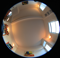
Zenith
Fig 21: A zenith shot
Load the images for the zenith, then select the menu
images > link HDR bracketed exposures. Click the align button, and create a preview.
Control points. If it does not align properly you can create control points to connect the same point on your zenith with a corresponding
point on a lateral image.
Masking. You can also make a mask to isolate just the middle of your zenith and nadir
(7 min 6 sec).Summary: you make a red to exclude the edges and green to force include the center, then optimize the image.
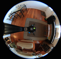
Nadir
Fig 22: A nadir shot
If you shot the nadir as described above with an offset tripod to get a shot that shows the area under the tripod, you can follow the method
described in the video (10 min 17 sec). to align these images with different
camera positions from the rest of the images. If you did not shoot an offset nadir and have the tripod obstructing the ground
(as seen in Fig 22 above),
you can follow the steps in PART VI. Nadir Patching to remove the tripod in Nuke.
Summary: Set control points (like with the zenith) to connect the same point on your nadir with a corresponding point on the ground plane of a lateral image.
Then run the optimizer with "viewpoint" correction checked for the nadir images. Next create a mask to exclude the tripod from the nadir, showing only the clean
part of the ground. Make a preview to see the results.
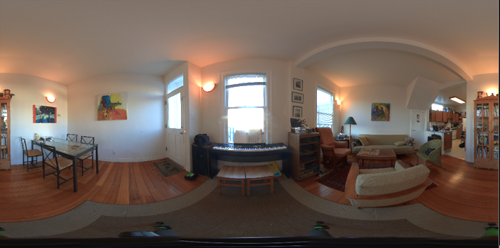
Create the panorama.
Fig 23: The resulting stitched 360 panorama.
Now we are ready to save the image. Go to the "create panorama" tab and choose the desired size. Google recommends a minimum of 14
megapixels (5300x2650) and max of 72mp (12,000 x 6000). Next select openExr for the HDR format, and under output check
"HDR panorama."
Click browse to set the file name and location. Finally, click the "create panorama" button to write the image to disc.
PART VI. Nadir Patching
Nadir patching with Nuke
As can be seen in the stitched panorama above (Fig 23) the tripod is visible at the bottom of the image. This would be very
hard to paint out because of the extreme stretching that happens at the top and bottom of a latlong image (which is incidentally
why the north and south poles are so long on a world map). So what we need to do is extract the view of the ground
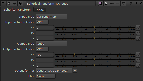
looking straight down (the nadir). In Nuke we can do this using a Spherical Transform node with its output
set to "cube" which converts our latlong image into 6 squares. To get the nadir we need to set the rx (the x rotation)
to -90 degrees. We then export this image to Photoshop as a 32bit EXR to preserve the HDR exposures.
Make sure you use a high resolution for the extracted square so as not to lose quality. If for instance your latlong image is
6000x3000 then your cubic image should be a 6k square.
Fig 24: Nuke's Spherical Transform node.
With this undistorted view of the ground (Fig. 25) we now can easily remove the tripod in Photoshop using
clone stamping, or even better, we can use content-aware. For content-aware, you just lasso the area and then hit shift-delete.
Content-Aware uses a Patch-based sampling method known as
"patch match" to perform
image completion on a selected area.
Geeking Out: Let's think for a moment about the broader applications of this.
Photoshop's content aware is one example of patch-based sampling in action,
but there are many exciting possible applications including texture synthesis,
image and video completion, image stitching, noise removal and more. One area where patch-based sampling and video completion techniques are clearly applicable is in compositing.
For instance, while this tutorial assumes we are creating a single image for CG image based lighting,
If you are instead working on a video sequence for 360 VR then you can create the nadir patch (as well as fixing seams)
in Nuke using techniques typically used to remove tracking markers (rotos, transforms, and trackers) or wire removal techniques
such as Nuke's built-in Furnace Core plugin
F_WireRemoval
which uses similar patch-based sampling techniques such as spacial sampling (taking the background information
from adjacent pixels in the current frame), and temporal sampling (taking the background information from frames on
either side of the current frame).
Fig 25: Photoshop's amazing content-aware in action.
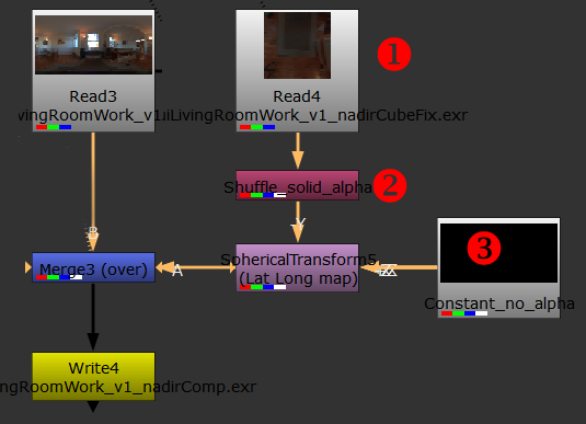
The final step is to take our patched nadir and transform it back into latlong format so we can comp it over our HDR pano.
As illustrated in Fig. 26 below, we read the patched nadir in from Photoshop (1) and add
a solid alpha to it with a Shuffle node (2). We then connect that to the -Y input of a Spherical Transform,
and connect a black Constant node (with no alpha) to all the other inputs (3).
Fig 26: Nuke node graph.
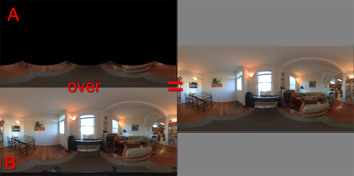
As illustrated in Fig. 27 below, this will give us a premulted latlong image of the patched nadir (A) which we can then simply comp over our original HDR pano(B),
giving us a our 360 pano with the tripod removed.
Fig 27: Comping the patched nadir over our 360 pano.
Below you can see the resulting pano in 360 view with the tripod removed. Use your mouse to rotate the view, and
check out the floor.
![[-]](../images/tutorials/collapse.gif "[-]") PART I. Intro: 360 HDR Panoramas
PART I. Intro: 360 HDR Panoramas![[-]](../images/thecure/collapse.gif "[-]")
 ) JPG
) JPG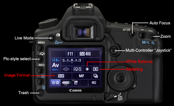
 on the camera (see the